Case Study / Skatepark Design
Skatepark design. Sketch to steel.
from paper to the skate floor.
The brief arrived as hand sketches. We turned it into seven park layouts in 3D for the client to choose from, modelled every ramp and box to size, then drew the welded steel frames sheet by sheet for the fabricator. The ramps are clad in sheet pressed from recycled plastic waste. The park is built and open.
- Tools
- SolidWorks / Sheet Metal
- Layouts
- 7 Options in 3D
- Panels
- Recycled Plastic Sheet
- Frames
- Welded, Galvanised Steel
At a Glance
One park, drawn to be built.
Live 3D
Turn the real models.
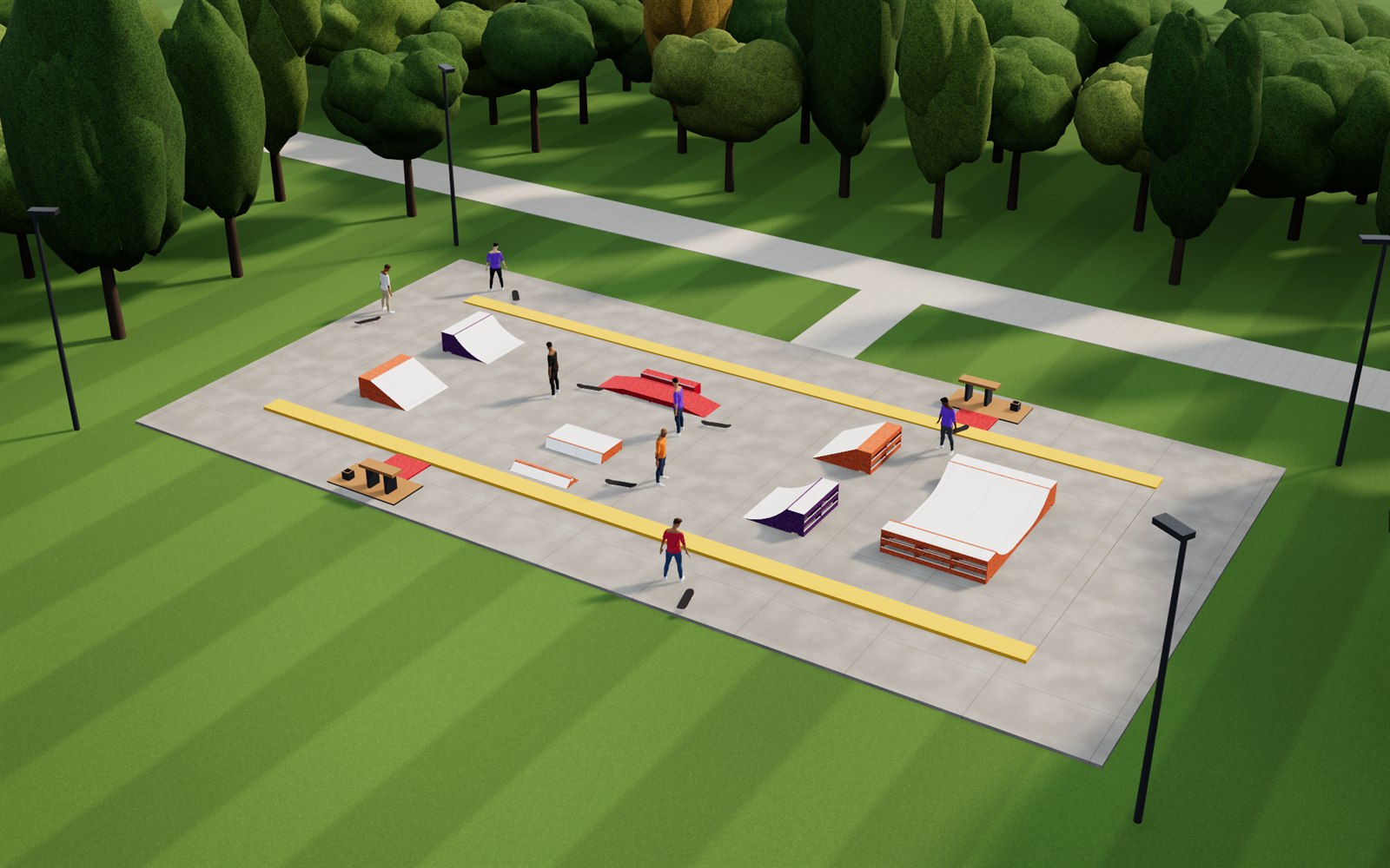
All seven layout options from the project, coloured to match the built park. Pick a layout, drag to turn it, switch to Drawing for line work, or use Section to cut through the ramps.
How It Was Built
Seven steps, one park.
The same route we take for any fabricated product: agree the layout in 3D, model each piece to size, then hand over shop drawings the fabricator can cut and weld from.
-
01
The Brief
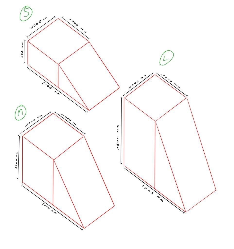
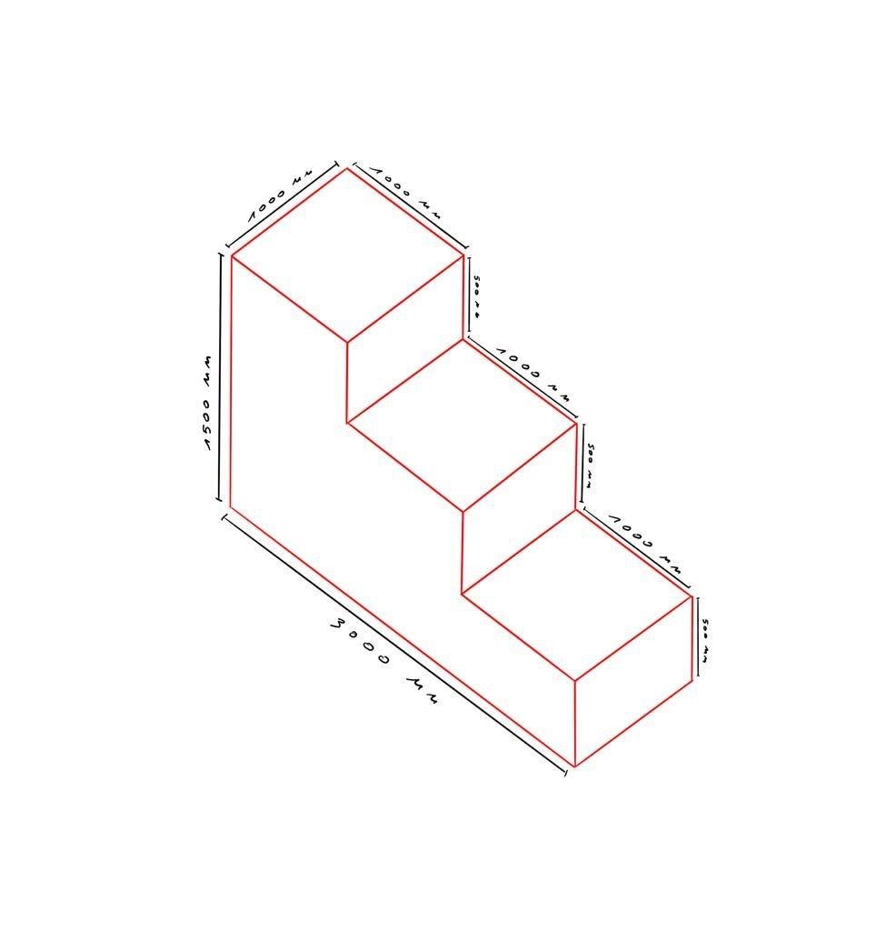
It started on paper: hand sketches of the pieces the park needed, banks, boxes, a wedge, a stair box and an L-wall, each with rough sizes. No CAD, no drawings, just the idea.
-
02
Layout Options
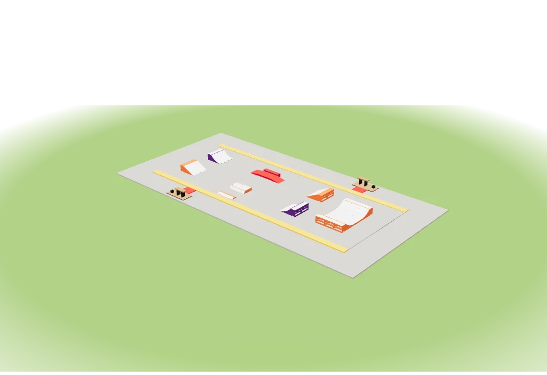
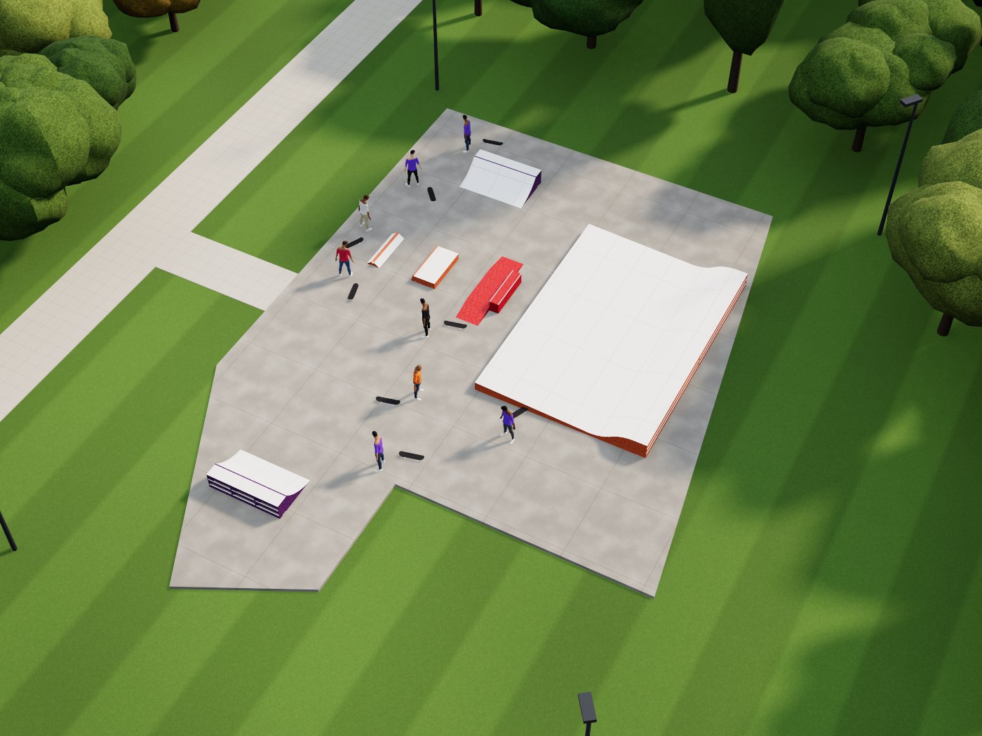
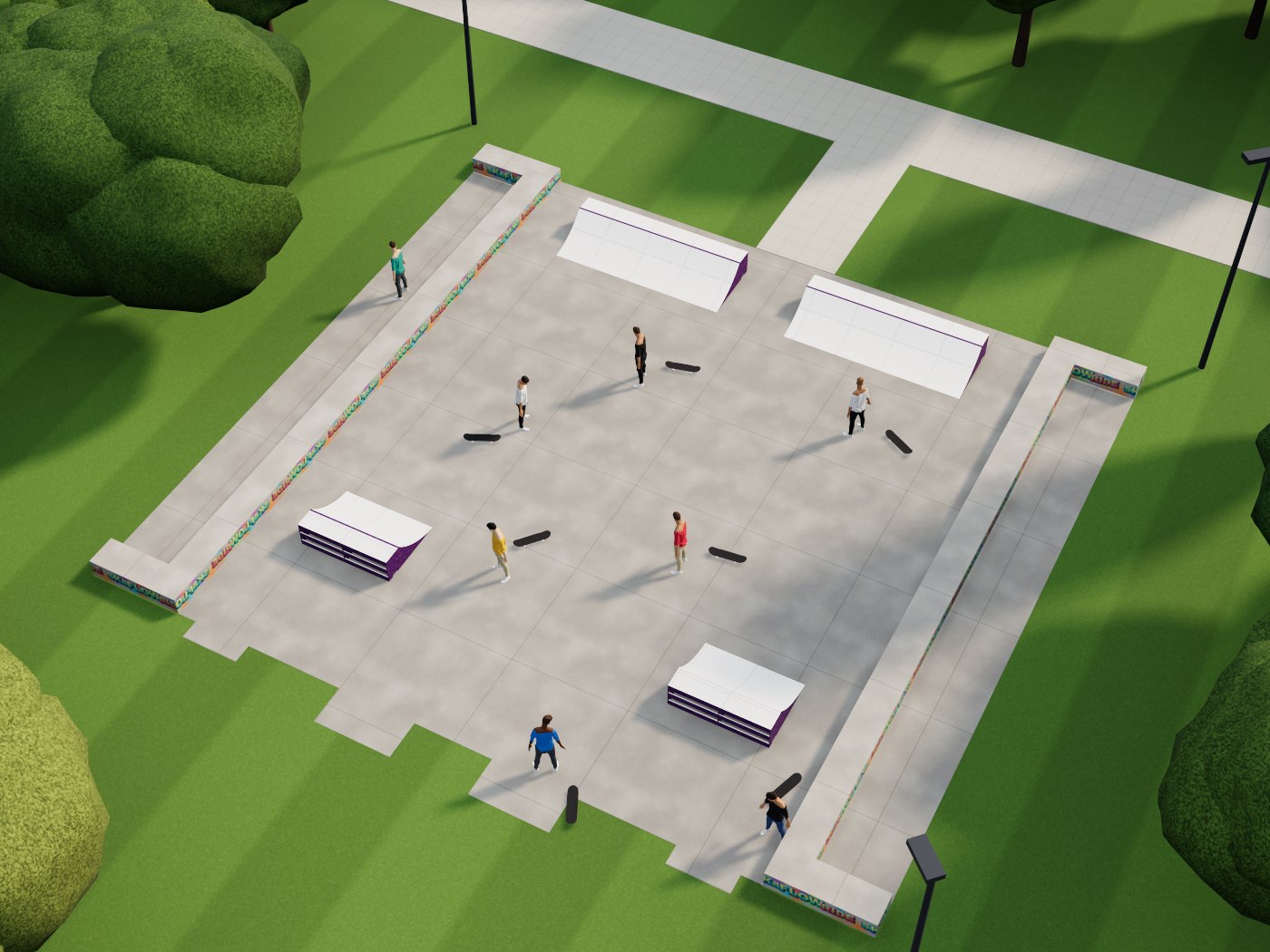
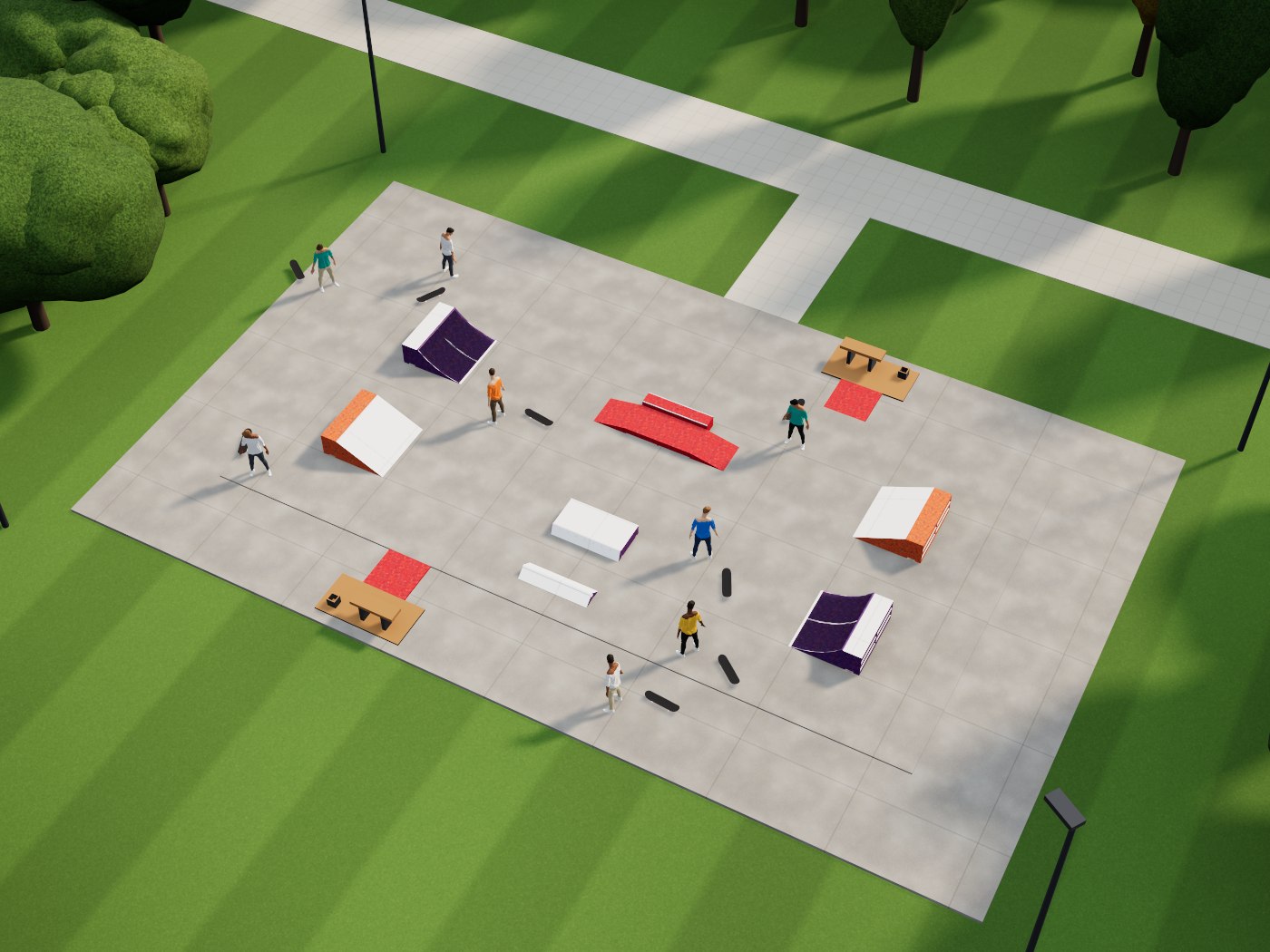
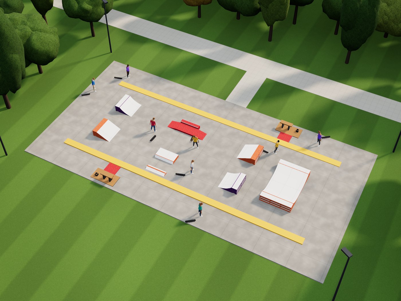
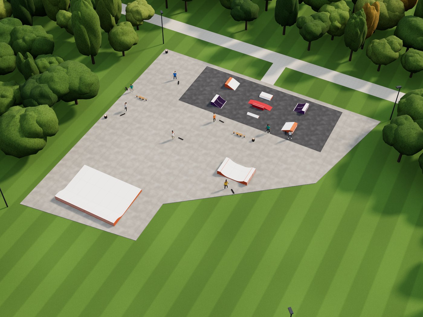
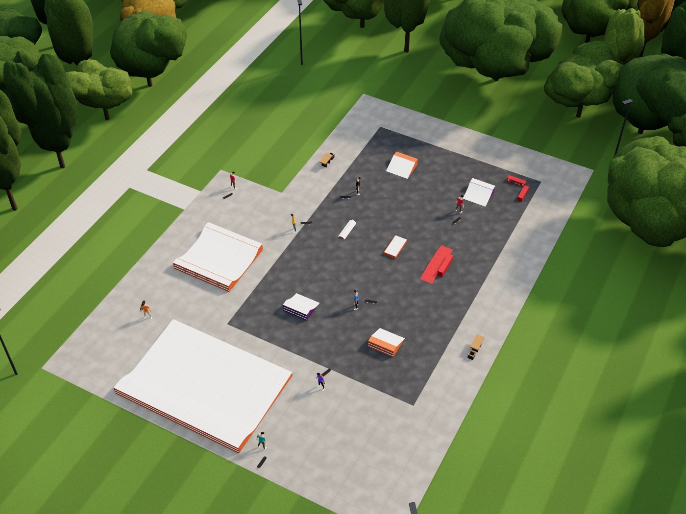
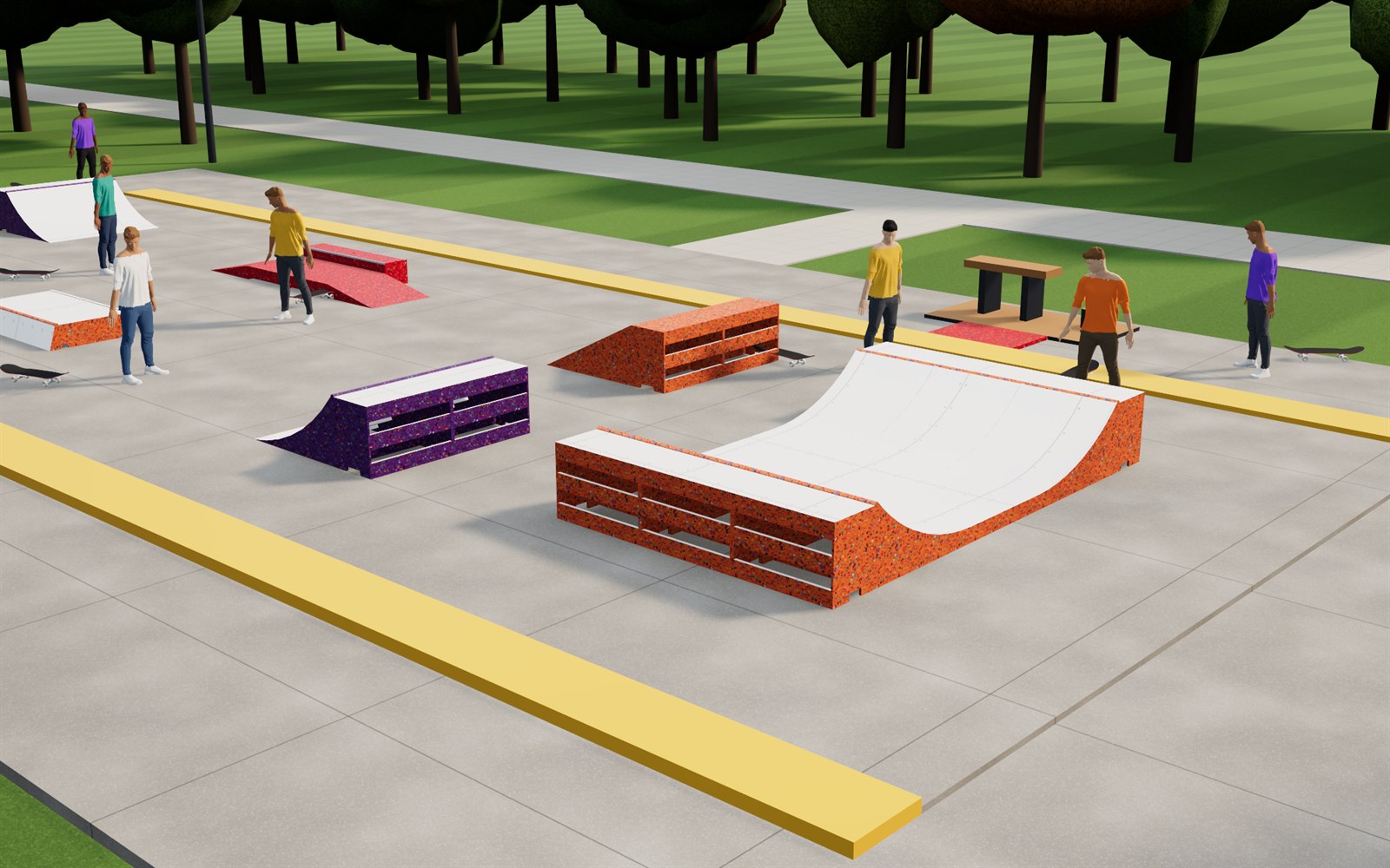
Seven layouts modelled in 3D, each on its real slab, from a walled 15 × 10 m plaza to a 40 × 40 m site. The client compared spacing, lines and the mix of elements on screen, and changed their mind for free, before anything went to production.
-
03
Every Element to Size
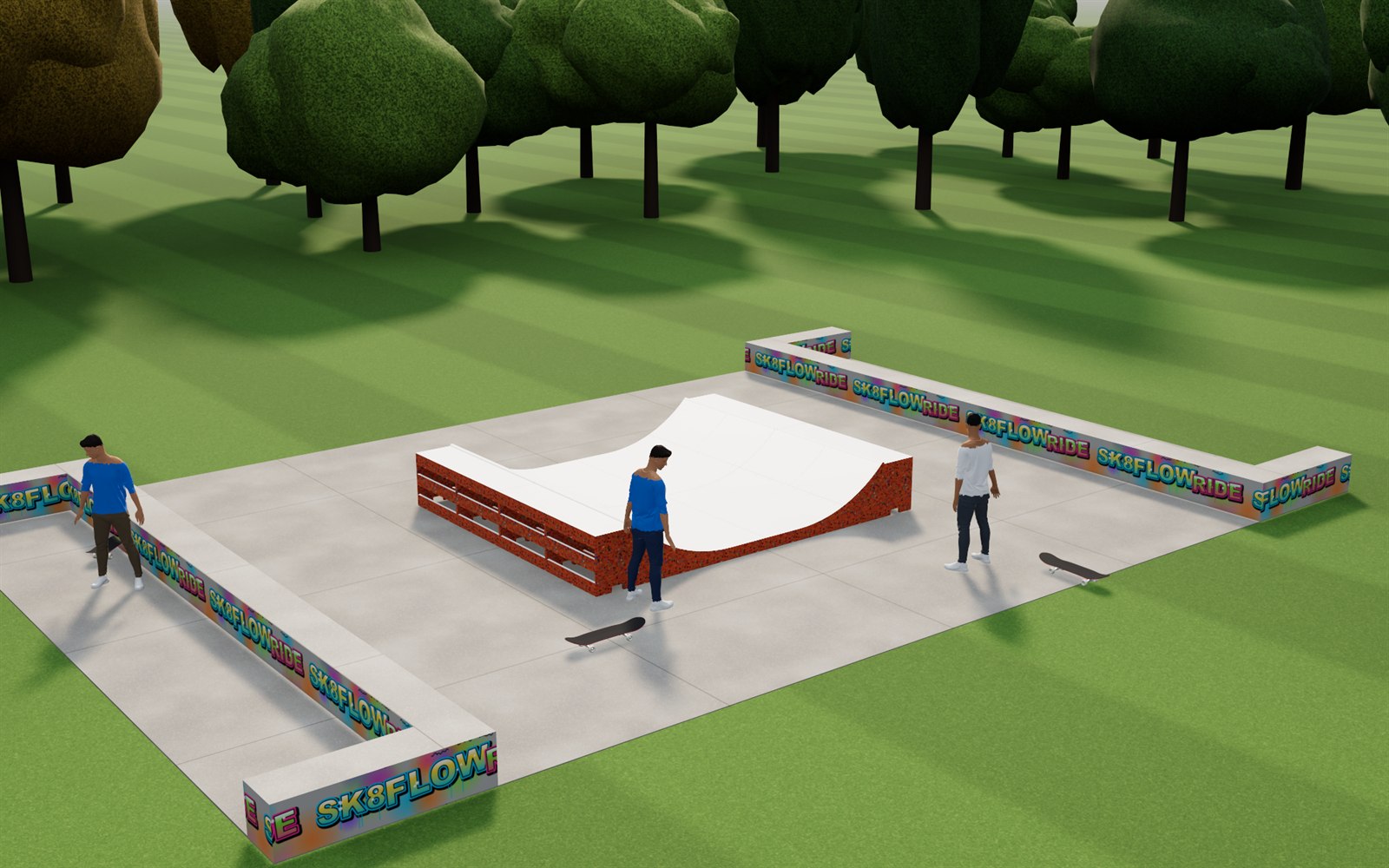
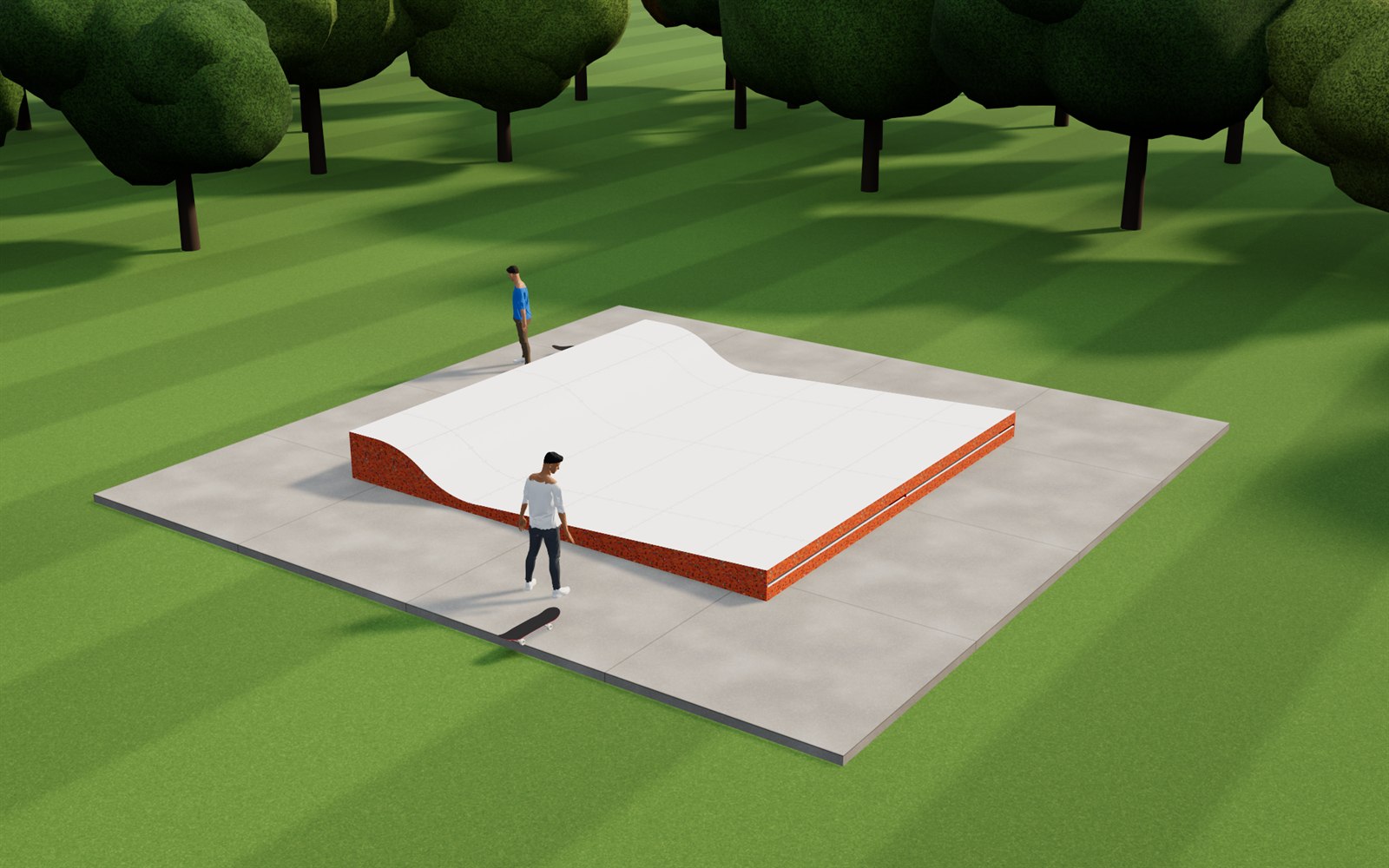
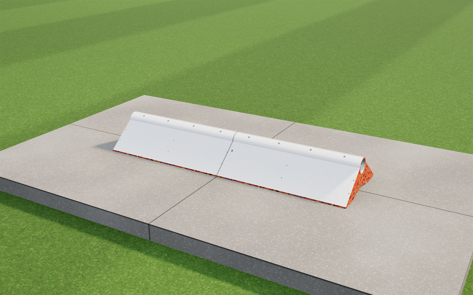
Each ramp modelled as its own solid, to real dimensions: a quarter pipe shown with a 1.78 m figure for scale, a 7 × 7 m wave ramp and a spine with steel coping along the ridge. The detail view shows how the pieces sit together on the slab.
-
04
Recycled Plastic
The ramps are clad in boards made from plastic waste: mixed flakes pressed into solid sheets, then cut to size for each panel. Waste that would have gone to landfill becomes the park. The speckled panels in the renders show that material.
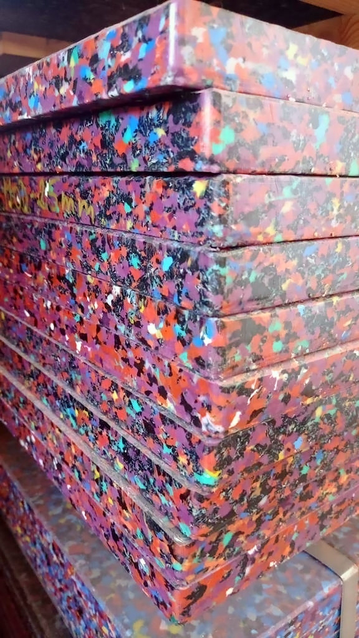
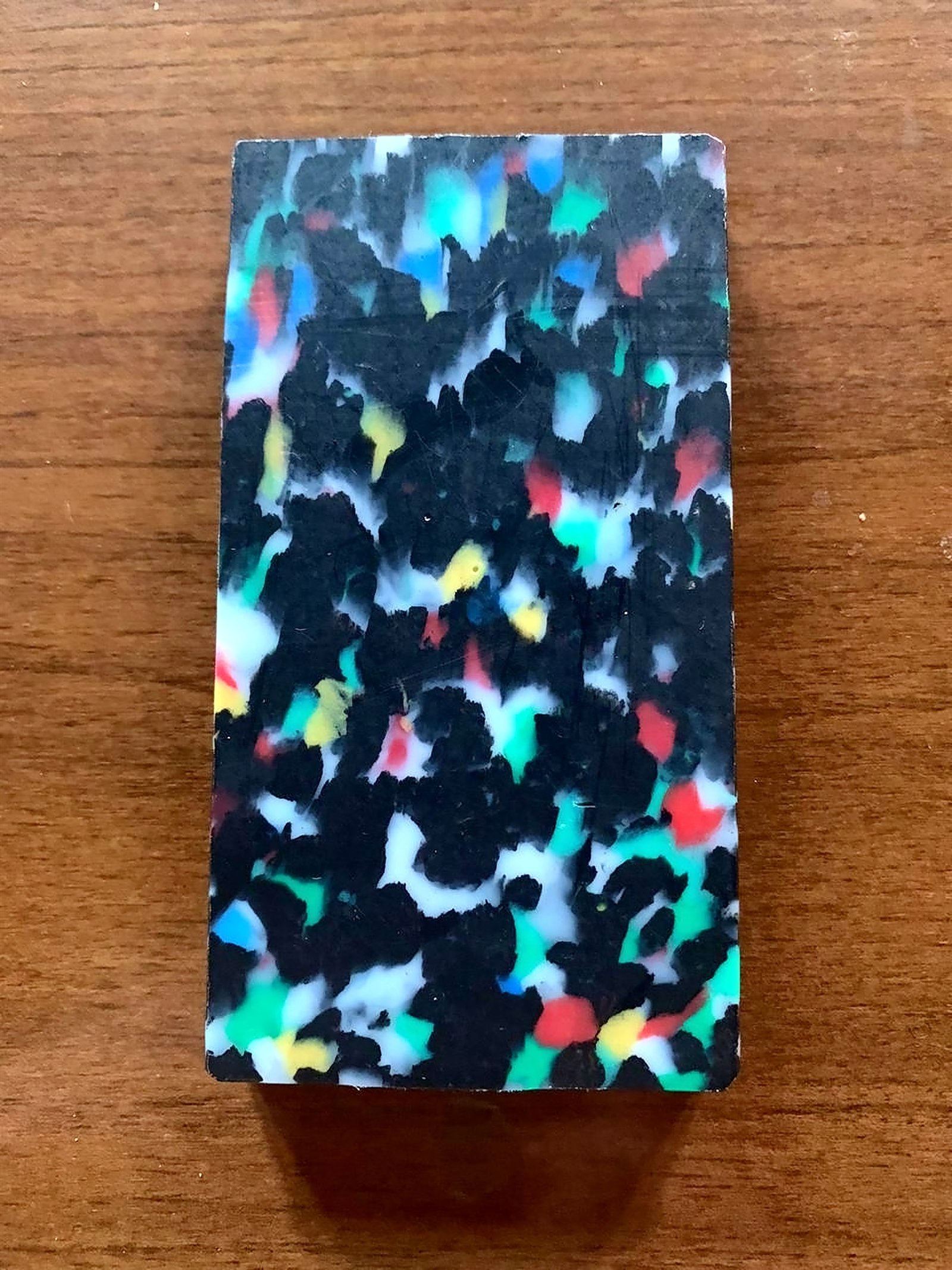
Sample / Recycled board - Source
- Plastic waste
- Made As
- Flakes pressed into solid boards
- Fitted
- Cut to size for each ramp panel
-
05
The Steel Frame
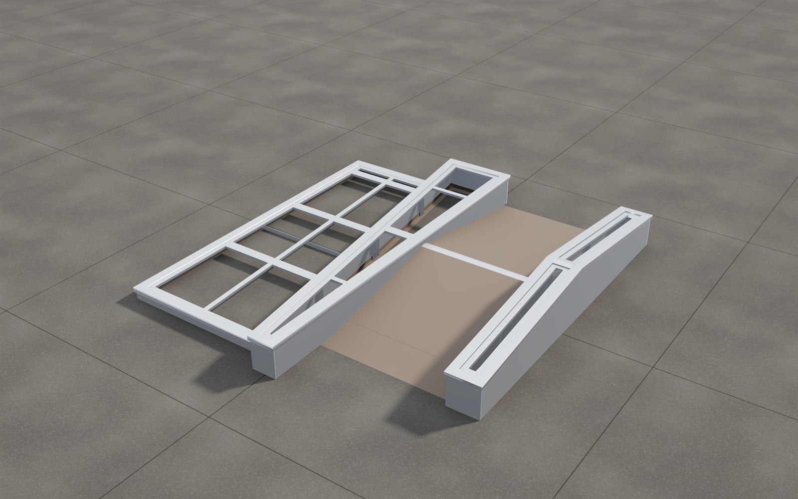
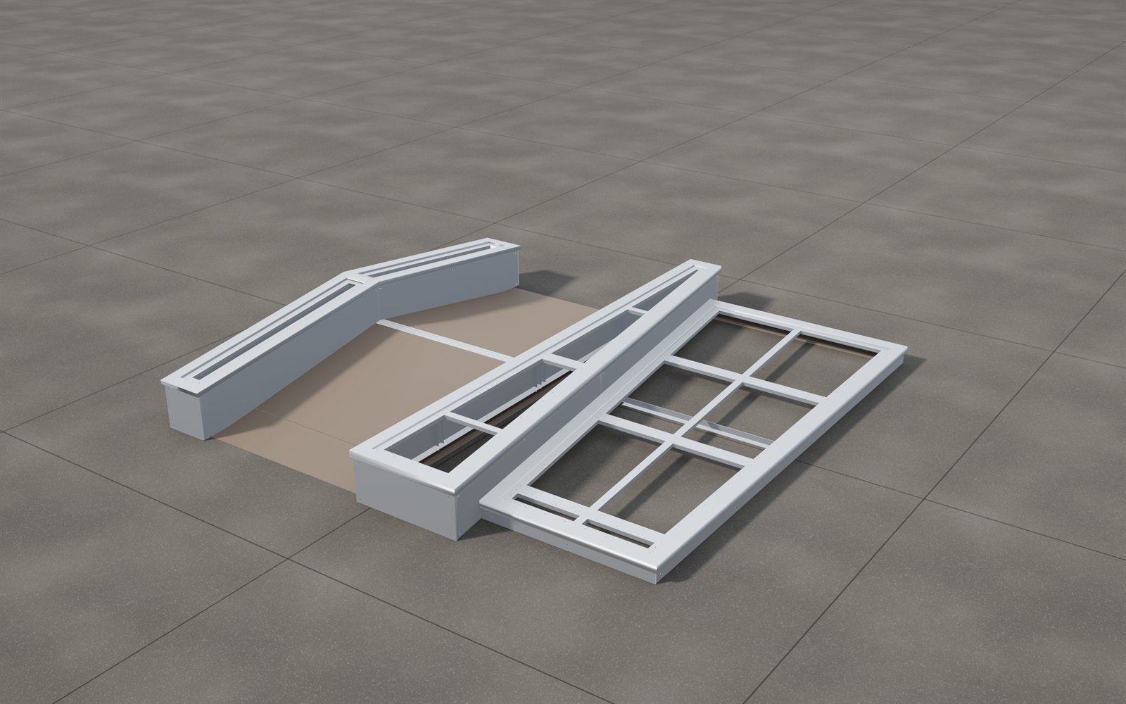
Under the panels sit welded frames in hollow section steel. The Wheelie Box alone is 38 parts under 31 part numbers, in 7 sub-assemblies, 4.5 m long. Every piece was drawn for the fabricator: assembly sheets with a written weld sequence, cut lists with lengths, angles and hole positions, and a BOM for each assembly. See it part by part
-
06
Fabrication
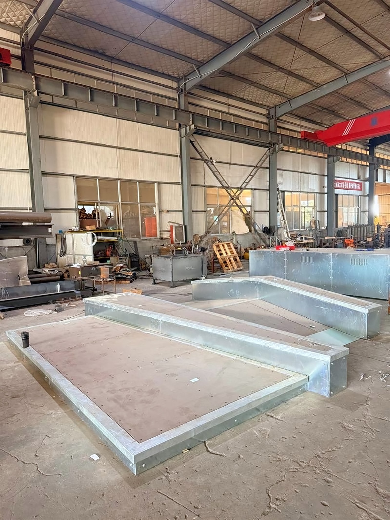
Cut and welded straight from the drawings, then galvanised, with the deck boards fitted in the workshop. No sketches on the shop floor, no guessing at lengths.
-
07
On Site
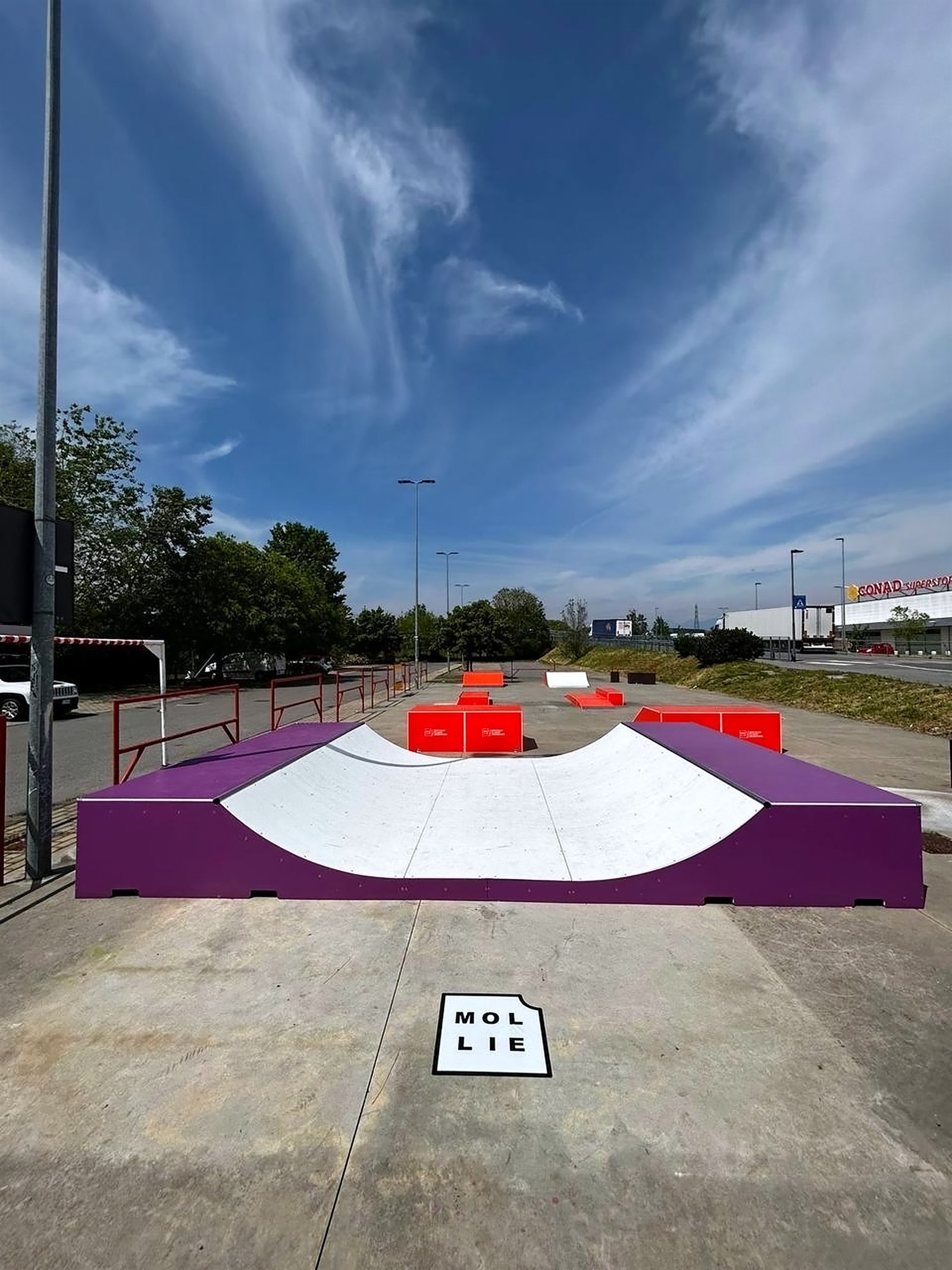
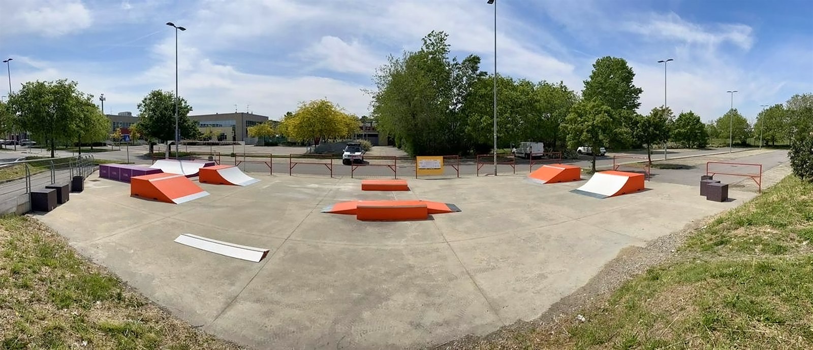
The finished park, installed and skated. The colours in the renders on this page are taken from these photos: white riding surfaces on purple, orange and red.
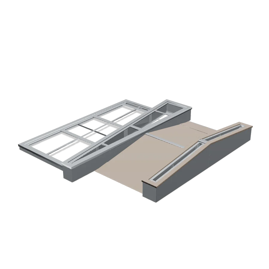
Part by Part
The Wheelie Box, broken down.
The steel model the drawings were made from. Turn it, press Explode to pull every tube and plate apart, then read the bill of materials and the sheets the fabricator built from.
1DCM-OS-01Deck plates6 parts
- 1.1DCM-PRT-01-001Plate, 14 mm, 2079 × 340
- 1.2DCM-PRT-01-002Plate, 14 mm, 2398 × 340
- 1.3DCM-PRT-01-003Plate, 14 mm, 340 × 295
- 1.4DCM-PRT-01-004Plate, 14 mm, 865 × 340
- 1.5DCM-PRT-01-005Plate, 14 mm, 2095 × 340
- 1.6DCM-PRT-01-006Plate, 14 mm, 2398 × 340
2DCM-SS-01Upper frame, welded on top of item 312 parts
- 2.1DCM-OS-02Weld frame: DCM-PRT-02, 05, 07 and 09, HSS 100 × 60 × 2
- 2.2DCM-OS-03Weld frame: DCM-PRT-12 to 19, HSS 60 × 30 × 3, cut 143 to 4295 mm
3DCM-SS-02Lower frame20 parts
- 3.1DCM-OS-04Weld frame: DCM-PRT-03, 04, 06 and 08, HSS 60 × 60 × 3 and 80 × 60 × 3
- 3.2DCM-PRT-10Short member, 220 mm
- 3.3DCM-PRT-11Short member, 220 mm
- 3.4DCM-OS-05Mirror of DCM-OS-04: DCM-PRT-20 to 23
- 3.5DCM-PRT-24Cross member, 60 × 30, 334 mm, qty 4
- 3.6DCM-PRT-25Cross member, 60 × 60, 200 mm, qty 2
- 3.7DCM-PRT-26Cross member, 60 × 30, 257 mm, qty 4
From the drawing set's top-level BOM: 38 parts, 31 part numbers, 7 sub-assemblies. Each frame is welded on its own, then the upper frame is stacked and welded onto the lower one.
What We Delivered
Everything the build needed.
One studio, from the first sketch to the last weld drawing: for the client who picks the layout, the shop that builds the frames and the crew that installs them.
- 01
Layouts in 3D
Seven park options on their real slabs, compared on screen before any steel was ordered.
- 02
Element Models
Every ramp, box, rail and bench as its own solid, to real dimensions, coloured to the built finish.
- 03
Renders
Presentation images of the park in its setting, for the client and for approvals.
- 04
Assembly and Weld Drawings
Assembly sheets with a written weld sequence for each steel frame.
- 05
Part Drawings and Flat Patterns
Single-part sheets with cut lengths and hole positions, and flat patterns for the laser.
- 06
BOMs
A bill of materials for every assembly, so the shop orders and cuts the right stock.
“The seller is highly skilled for what they do, follows direction to the tee. Working with him the second time and he did not disappoint.”
“I work with this supplier often. It goes very well and I will certainly do more jobs with him. Recommended.”
“I was a very good experience working with him I recommend working with him”
Fixed quote within 1 working day
Ready to build your part?
any format works.
Send a sketch, a photo, a PDF or a STEP file. Scope, fixed price and a delivery date back within one working day.